 Inventions & Experiments
of Nikola Tesla
Inventions & Experiments
of Nikola Tesla
British Patent 179,043 - Improved Process of and Apparatus for Production of High Vacua
http://www.rexresearch.com/teslatur/turbine2.htm#vacuum
March 24, 1921
I, Nikola Tesla, Electrical and Mechanical Engineer, citizen of United States of America, of No. 8, West 40th Street, New York, NY, USA, do hereby declare the nature of this invention and in what manner the same is to be performed, to be particularly described and ascertained in and by the following statement:
In the development of power by thermodynamic prime movers, as steam engines and turbines, a low back pressure is essential to good economy, the performance of the machine being increased from fifty to one hundred per cent, by reducing the absolute pressure in the exhaust space from fifteen to about one pound per square inch. Turbines are particularly susceptible to such improvement and in their use for operation of power plants and manufacturing establishments the attainment and steady maintenance of high vacua has assumed great importance, every effort being made to better the conditions in this respect. The gain effected by this means is, in a large measure, dependent on the initial pressure, characteristics of the prime mover, temperature of the cooling medium, cost of the condensing apparatus and many other things which are all well-known to five to six per cent of fuel for each addition inch of vacuum is often closely approximated in modern installations, but the economic advantages are appreciably lessened when higher vacua are applied to existing machines purposely designed to operate with lower ones. More especially is this true of a turbine in which the reduction of back pressure merely increase the velocity of exit of the vapors without materially augmenting the speed of their impact against the vanes, buckets, or equivalent organs, when the loss of kinetic energy in the exhaust may offset a considerable portion of the useful work. In such cases some constructional changes in the turbine and auxiliaries may have to be made in order to secure the results here contemplated but the additional capital used for this purpose will be profitably invested. Summing up the situation it may be generally stated that a more or less substantial reduction of fuel cost can be made in most of the existing power plants by the adoption of proper pumping apparatus and establishment of working conditions nearly corresponding to those of an ideal condenser.
The chief difficulties which have thus far retard advancement in this direction are encountered in the enormous volumes of the air and vapor at very low pressure as well as unavoidable leaks in the condenser, pipe joints, valves, glands and stuffing boxes. At present exhaustion is usually accomplished by reciprocating pumps and these, on account of the necessarily low speed of the pistons are large and, moreover, incapable of satisfactory performance in the presence of big leaks. As a direct result of this the condensing plant is both bulky and expensive and, worse still, its size and cost increase entirely in disproportion to the results attained. To illustrate -- the outlay involved in the installment of condensing apparatus for a twenty-eight inch vacuum is more than double that required for a vacuum of twenty-six inches and these draw-backs are still more emphasize with the further reduction of the back pressure. Rotary pumps and jets of water and steam are also used in the production of vacua, but without marked qualitative advantages.
I have achieved better success in departing from the customary method of removing the air and entrained steam from the condenser by bodily carriers as jets, reciprocating pistons or rotating vanes, and availing myself of the properties of adhesion and viscosity which, according to experimental evidence are retained by the gases and vapors even at very high degrees of attenuation. This new process is rendered practicable through a pump, the underlying principle of which is fully explained in my British Patent 24,001 of 1910, but which is modified as hereinafter described and when run at the very great peripheral speed of which an unloaded system is capable, exhibits two remarkable and valuable properties. One of these is to expel the rarefied fluids at such an immense rate that a hole of some size can be drilled in the condenser without much effect on the vacuum gauge. The other is to draw out the fluids until the exhaustion is almost complete. A machine of this kind, constructed in stages, is alone sufficient for the production of extremely high vacua and I believe this quality to be very valuable inasmuch as it is not possessed to such a degree by other types of commercial pumps, which have come to my knowledge. I have also found that inserting my pump between the condenser and a "dry air" or other pump produces a very effective combination. This combination is especially advantageous from the practical point of view as good results can be secured with a single stage and the installment of my device calls for but a slight change in the steam plant. The benefits derived are twofold; a higher vacuum is attained and, what is perhaps more important, the frequent and unavoidable impairments of the same, which seriously affect the economy, are virtually eliminated. My pump makes possible the maintenance of high vacua even when the percentage of air or other fluids carried with the steam is very great and on this account should prove particularly useful in the operation of mixed fluid turbines.
My invention will be more fully understood by reference to the accompanying drawing in which Figure 1 shows a multi-stage pump of this kind in sectional views, and
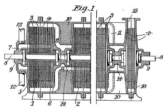
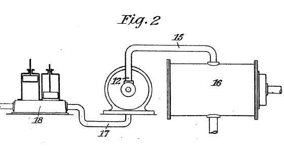
Figure 2 illustrates it use in connection with a double-acting reciprocating pump.
In the first figure, 1, 2, etc., are rotors each of which, as 1, comprises a number of relatively thin disks 3,3, etc., separated by star-washers 4,4, etc., and held together by rigid endplates 5 and 6 on a sleeve 7 which is fitted and keyed to a shaft 8, rotatably supported in bearings 9,9. The rotors are contained in separate chambers of a common structure 10, which surrounds them and is made up of parts held together by flange connections. Beginning with the fist stage at 1, the rotors diminish in width, each following being made narrower than the preceding, for obvious economic reasons. All the thin discs, as 3,3, etc., and left-hand endplates, as 5, are provided with the usual central openings, but the right-hand end plates, as 6, are blank. The individual chambers, containing the rotors, communicate with each other through channels, as 11, extending from the peripheral region of one to the central part of the next, so that the fluids aspired at the intakes 12, 12 are compelled to pass through whole series of rotors and are finally ejected at the flanged opening 13 of the last chamber. In order to reduce leakage along the shaft, close-fitting joints or locks, as 14, are employed which may be of ordinary construction and need not be dwelled upon specifically. The number of stages will depend on the peripheral velocity and the degree of exhaustion, which it is desired to secure, and in extreme cases a number of separate structures, with intermediate bearings for the shaft, may have to be provided. When found preferable the pump may be of the double-flow type, when there will be no appreciable side thrust, otherwise provision for taking it up should be made.
The modifications in details of construction, to which reference has been made, consist in the employment of smaller spaces between the discs than has hitherto been the case, and of close side-clearances. To give a practical example, I may state that spaces of 3/64 of an inch will be effective in the production of very high vacua with discs of, say, 24 inches in diameter. I also make all discs tapering, when necessary, in order to operate safely at an extremely high peripheral velocity which is very desirable since it reflects both on the size of the machine and its effectiveness.
The arrangement represented diagrammatically in Fig. 2 is especially suitable and advantageous in connection with existing steam plants operating with high vacuum and permits the carrying out of my improvements in a simple manner and at comparatively small cost. In this case my pump, which may have but one rotor of the above description, is connected with its intake 12, through a pipe 15, to the top of a condenser 16, and with its discharge opening 13, by pipe 17, to the suction duct of a reciprocating dry air pump 18. It goes without saying that in actual practice connections 15 and 17 will be short mains of very large section as the volume of fluids to be pumped may be enormous.
The operation will be readily understood from the foregoing. The intakes 12 being joined by an air-tight connection to the vessel to be exhausted and the system of discs run at very high peripheral velocity the fluids, by reason of their properties of viscosity and adhesion, are drawn out of the vessel until the degree of rarefaction is attained for which the apparatus has been designed. In their passage through the series of rotors the fluids are compressed by stages and ejected through the opening 13 at a volume greatly reduced. The vacuum produced by this means may be extremely high because of the apparently unique properties of the device pointed out before and as the fluids, irrespective of their density, are sucked out at an excessive speed, leaks through the glands, stuffing boxes and connections are of but slight effect.
In the arrangement shown in Fig. 2 my pump serves to evacuate the condenser much more effectively and by compressing the fluids at the intake of the reciprocating pump improves the performance of the same. The installment of the devise in existing plants does not call for extensive alterations in the same and will result in a notable saving of fuel. My pump may also be advantageously employed in place of a steam jet in conjunction with a small condenser in which case it will be of insignificant dimensions and economical in steam consumption.
Write a comment
John Wilkinson (Friday, 03 June 2016 19:44)
This is another use of the Tesla Turbine!
Jeremiah Ferwerda (Sunday, 23 June 2019 18:02)
This is for reducing back pressure in the exhaust of the turbine! In conjunction you can have a thermodynamic transformer that is capable of reaching 100% efficiency.