 Inventions & Experiments
of Nikola Tesla
Inventions & Experiments
of Nikola Tesla
US186,799 - Process of and Apparatus for Balancing Rotating Machine Parts
http://www.rexresearch.com/teslatur/turbine2.htm#186799
12 October 1922
I, Nikola Tesla, do hereby declare the nature of this invention and in what manner the same is to be performed, to be particularly described and ascertained in and by the following statement:
In the operation of machinery the accurate balancing of the rotating parts is of great economic importance as vast sums of money are annually expended on account of deficiencies in this respect resulting in loss of power, undue wear and tear, interruption of service and accidents of a more or less serious nature.
Prior to the development of modern high speed apparatus static balancing was depended upon entirely and even now this is frequently the case. The steadily increasing tendency in the direction of high speed brought on the necessity of dynamic balancing and various forms of apparatus for this purpose were devised.
The process I have invented enables this to be done quickly and with a high degree of accuracy and, briefly stated, consists of rotating the body to be balanced, yieldably supported, at a suitable speed and removing excess material from its heavier side by abrasion, until the desired degree of perfection of balance is attained.
As means to this end I may employ a grinding wheel, a sand-blast or jet of other abrasive substance. It might be naturally inferred that the contact of an emery or carborundum wheel with a rapidly whirling machine part would be productive of dangerous shocks and vibrations, and also that grinding at speeds much higher than the usual could now be satisfactorily accomplished. But although these theoretical assumptions appear sound, I have encountered no difficulties of this kind and have performed the operation with the greatest facility and success. This I attribute to the inertia and momentum of the spinning body which makes it insensitive to such asynchronous disturbances as the wheel might produce. However, in certain cases it may be more convenient or preferable to effect the removal of the excess material by a high velocity jet of abrasive material by a high velocity jet of abrasive substance applied tangentially to the part to be balanced. In order to attain the best results it is essential that the latter, when rotated, shall be capable of an appreciable displacement of its center of gravity from the axis of symmetry. This is accomplished by supporting it on a shaft of suitable flexibility, or, if its own shaft is not sufficiently flexible, in bearings yieldably mounted. It is furthermore of great importance, in order to avoid vibrations which would interfere with the proper application of the process, that the speed at which the grinding is effected should bear a definite relation to the critical, corresponding to the fundamental natural vibration, and the following rule should be observed: If the system is run in two bearings the grinding wheel should be an odd multiple or submultiple of the critical. If, on the other hand, the system is supported on one side only, the speed should be an even multiple or submultiple of the critical.
When the structure is revolving at the proper speed I bring the abrasive wheel into operative contact with it at a peripheral or other suitable region and grind off material. As the action continues, the flexure of the shaft diminishes until, finally, its center of symmetry coincides with the center of gravity of the system, or nearly so. This can be noted in many cases by a competent operator without the use of a special device, but suitable visible or audible means may be employed for the purpose.
Preliminary to the application of the process it is advisable to run the part at a very low speed and true it with the wheel. If there exists appreciable flexure of the shaft when the system rests horizontally, the grinding may be done in a vertical position when it is in static balance. A part to be run on a stiff shaft may be mounted on another of suitable flexibility; and as there exist limitations in the accuracy of fitting a cylindrical sleeve, I may employ a tapering one to secure greater precision. However, satisfactory results can generally be obtained in arming the rigid shaft with flexible extensions or holding it in bearings suitable supported. In all cases it is desirable to flood the latter with lubricant of considerable viscosity. When balancing parts to be run at a high temperature they may be inclosed in a casing in which approximately the same temperature is maintained, an opening being provided for the introduction of the abrasive wheel or jet.
My invention will be clearly understood by reference to the accompanying drawings illustrating a form of apparatus I have devised for the quick and convenient balancing of such bodies as rotors of my steam and gas turbines.
Figure 1 shows the general arrangement of the component parts comprising, a casing with an opening on one side, lathe mechanism for feeding the wheel, a tachometer enabling instantaneous readings of the speed to be taken, an instrument for continuous visual indication of the degree of accuracy attained and a preheater of the elastic medium such as compressed air used in the operation;
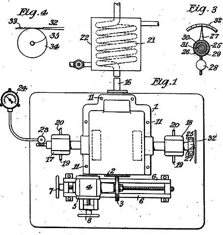
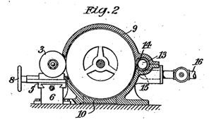
Figure 2 represents a section through the casing in the plane of a rotor disc, exposing said opening and also the turbine nozzle;
Figure 3 is a view of the essential parts of the balance-indicating instrument and,
Figure 4 illustrates the manner in which a jet of abrasive substance is applied when carrying out my process.
Calling attention specifically to the first names 1 is a casing, enclosing an air- or steam-driven rotor to be balanced, and shown as open at 2 for the purpose of permitting the wheel 3 to be brought into operative contact with the surfaces to be ground. Any suitable drive may be employed but I ordinarily resort to the electric, mounting the wheel directly on the shaft of a motor 4 fixed to a lathe carriage 5 which slides on rails 6, 6 and is provided with means 7 and 8 for feeding the wheel, respectively, along the axis of the motor shaft and at right angles to the same.
As shown in Figure 2 the casing is split horizontally on the centerline in two castings 9 and 10, carefully planed so as to insure their coming into the same position whenever put together, lateral displacement being prevented by dowel-pins 11, 11 (Figure 1) which are driven tight either in casting 9 or 10. These are enlarged and bred out on one side and into the hole is snugly fitted a hollow cylinder 13 with nozzle 14 and intake opening 15 directly connected to the supply line 16 provided with a suitable control valve. The opening at 2 for the entrance of wheel 3 is shown as a simple opening through the casing, but in certain cases I introduce the wheel through an enlargement shown in Figure 2 on the right side, which is often convenient when balancing a rotor in its own casing.
Referring again to Figure 1 the bearings 17 and 18 are also divided horizontally in the plane of the casing joint and their upper and lower parts may be integral with the corresponding casting 9 and 10 for the purpose of saving labor and time. The lower parts of the bearings are equipped with oil supply and discharge pipes 19 and 20.The supply pipe 16 is shown as connected to a coil 21 of a heater 22 which is equipped with a valve for controlling the flow of the heating medium and may be of any known construction. Q worm drive 23 is provided on one end of the rotor shaft for operating the tachometer 24 through a flexible connection. This device may be of any make but I find it advantageous to use the air friction type. On the other end of the shaft is mounted the balance indicator 25 (shown in detail Figure 3) consisting of a member 26 with a pointer 27 on the top and an adjustable mounted weight 28 on the bottom. This member is supported on the outer race 29 of a ball-bearing 30, the inner one 31 being fixed to the shaft, and is thus capable of oscillation. The rotary effort necessary to produce a given deflection of the same being determined by the position of the weight. A graduated scale 32 is attached to the stationary part of the instrument which is placed conveniently for observation by the operator.
Substantially the same apparatus, with the exception of wheel 3, may be employed in connection with the device diagrammatically illustrated in Figure 4,in which a suitable fixture 32 projects a jet 33 of abrasive substance tangentially upon the body 34 to be balanced which is supported on a flexible shaft 35. In this case of course the fixture is mounted on carriage 5 to enable feeding in two directions.
Substantially the same apparatus, with the exception of wheel 3, may be employed in connection with the device diagrammatically illustrated in Figure 4, in which a suitable fixture 32 projects a jet 33 of abrasive substance tangentially upon the body34 to be balanced which is supported on a flexible shaft 35. In this case of course the fixture is mounted on carriage 5 to enable feeding in two directions.
The balancing is done as follows: The rotor being in position for grinding the casting 9 and covers of bearing 17 and 18 are put in place, lubricant forced through pipes 19 and 20 and a motive fluid as compressed air, admitted to nozzle 14, its quantity and temperature being regulated, respectively, by valves on supply pipe 16 and heater 22. The fluid, in traversing the rotor and exhausting through the lower casing imparts motion to the former and brings it up to the desired speed, ascertained by reading of tachometer 24. The abrasive wheel 3 is now fed across the rotor and the indication of the balancing instrument on the graduated scale noted. At the start the deflection of the pointer is likely to be considerable due to the fact that any, however slight vibration of the shaft, increases greatly the pressure on the balls and consequently the torque of the instrument. As the balance improved the deflection diminishes until finally the pointer reaches the zero of the scale indicating that the desired degree of perfection of balance has been attained. As a crucial test the operator may then run the rotor at about the critical speed. This should cause no appreciable vibration or effect on the balance indicator which, instead of carrying a weight, may be equipped with a spring for producing the required pressure on the ball-bearing and opposing the torsion.
When bodies not adapted for rotation in the manner shown are to be balanced, they will be driven independently by belt, electricity or other means, care being taken that no disturbing vibration from them is transmitted to the apparatus. In order to preserve intact the peripheral boundary, if this is essential, I grind the material off from some other place and when desirable, I make a special provision to this end in the design and construction of the part.
I have found my process very valuable in the balancing of high-speed steam and gas turbine rotors but I have used it successfully in a great variety of cases and do not limit its application to any kind of apparatus.
Having now particularly described and ascertained the nature of my said invention and in what manner the same is to be performed, I declare that what I claim is: -- [ Claims not included here]
Write a comment