 Inventions & Experiments
of Nikola Tesla
Inventions & Experiments
of Nikola Tesla
Rare notes from Tesla on Wardenclyffe
By Leland Anderson
http://www.tuks.nl/wiki/index.php/Main/TeslaRareNotesOnWardenclyffe
Originally printed in: Electric Spacecraft Issue 26 Apr/May/Jun 1997

http://www.tuks.nl/wiki/index.php/Main/TeslaRareNotesOnWardenclyffe
Rare notes from Tesla on Wardenclyffe
By Leland Anderson
(Originally printed in: Electric Spacecraft Issue 26 Apr/May/Jun 1997)
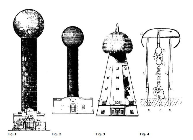
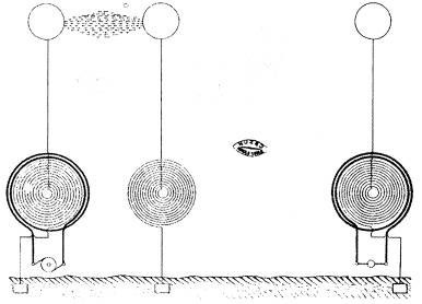
Tesla's tower at Wardenclyffe is perhaps as enigmatic as the prodigal genius was himself. (Figs. 1-3 show in part a conceptual evolution of the tower.) While Tesla aficionados have scraped the archives and haggled with politicos to obtain even the minutest revelations on how this device might have actually been capable of transmitting energy worldwide, nobody seems to know how this was to be effected. In what follows, the contents of some practically-uncirculated papers, that Leland Anderson managed to obtain, are reproduced in full.
The first note, written on Waldorf-Astoria letterhead, discloses Tesla's reasoning behind some of the dimensional specifications required in an early design for the tower which he claimed would be capable of transmitting electricity worldwide by means of earth resonance. The letters reprinted here were all written in 1901. Actual construction of the tower did not start until December 12, 1901.

http://www.tuks.nl/wiki/index.php/Main/TeslaRareNotesOnWardenclyffe
New York May 29, 1901
from old note
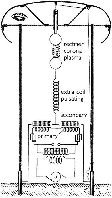
In annexed sketch [See Fig. 4.] a terminal C in form of a roof is supported on conducting supports L1L1. Terminal C1 is adjustable and in contact with structure of roof, or terminal C1. A resonating system C2ℓSE discharges with C1 and produces oscillations in system CL1L1E1E1.This arrangement obviates necessity to support roof or terminal C on insulated supports.
Now in a sketch or scheme the difficulty will be probably to get the oscillations of the free system CL1L1E1E1 slow enough to be very effective in transmission through earth as in my system. The length of conductors in the free system should be λ/4, and the length of the discharging current should be 3/4 λ or n/4 λ eventually, n being uneven number.
Suppose, to get an idea, we take C = 10,000cm. This is realizable. Then we have
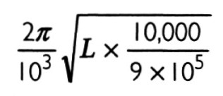
the period of the system. We should have vibration not much quicker than 100,000 and to satisfy this L would have to be:
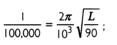
L = 9 x I05/4 = 225,000 cm. Calculated it would appear that the supports L would have to be about 600 feet. The arrangement would be OK with quick oscillation. The self-induction of a straight conductor is L' = 2l'[loge (2l'/r) - 0.75]. Now, take /'= 300 ft = 9000 cm. If we want to use iron pipes 4" diam. r = 5 cm. Then 2l'/r = 3600 and from this I find L' = 134,000 cm. Again taking the length 600 ft we would get inductance probably 268,000 cm. To get lower frequencies, evidently in above scheme self-induction must be increased.
P.S. The charging and discharge current may even be of different period and both vibrations used to excite receiver.
Leicester, North Carolina 28748 USA 5
The person who proofread the decipherer's notes found fault with Tesla's analysis, stating that in order to limit the induction to 225,000 cm, the tower would need to be nearly three times taller than Tesla anticipated, or 1,404 feet high.
As it was, the Wardenclyffe Tower project was very large, and involved numerous construction crews. The following note was sent to Margaret Cheney, while she was writing Tesla's biography.
Wardenclyffe Project
Reference has been made by O'Neill and contemporary newspaper accounts of the large crew that Tesla had working for him at Wardenclyffe. Instead of just referring to the "large crew" as such, it might be a good idea to sprinkle in a few names of Tesla's direct assistants. They were:
Willie Eppersteiner
Hartmann
Johnnison
Lindeke
Meyer
Alfred Peters
Seibel
Mr. Uhlman (815 N. 12th St., St. Joseph, MO)
Wagner (Tesla's glass blower)
Letters
The next three letters illustrate, to a small degree, the breadth of the concerns Tesla had while overseeing the building of his tower. The first two are written to the architect, Stanford White; the third is to the company that was to furnish the building's boilers.
New York Aug. 28 1901
Mr Stanford White
160 fifth ave. New York city
My Dear Standford:
I have seen the American Bridge people today to ascertain wether they will be able to construct the cupola of my building without much delay. As this item will consume longest time, it is necesary to take premiliminary steps so that the work may begin just as soon as you have passed upon the plans. I believe that American Bridge Company is the best to concern to deal with this matter, but I beg you not to pay attention to my suggestion, if you think otherwise.
The Bethlehem Steel Company will furnish me the shits, but I cannot give the order until we have agreed upon all details.
With kind regards,
Yours very sincerely,
N.Tesla
6 Electric Spacecraft Issue 26 Apr/May/Jun 1997
RARE NOTES FROM TESLA ON WARDENCLYFFE
New York, Aug. 30th, 1901
46 & 48 East Houston Str.
Mr. Stanford White
160 Fifth Ave.
New York City
My Dear Stanford:
Many thanks for your suggestions. I am writing to Mr. Powell today. Perhaps he will be able to clear the land altogether. I want you to understand that I went to the American Bridge Company simply because of my anxiety to have the work pushed through as fast as practicable. I am only too glad to follow your advice and beg you to consider yourself absolutely free in your choice and arrangements regarding this work.
Yours very sincerely,
N. Tesla
-----------------------------------------------------------------------------------------
New York, Sep. 12th, 1901
46 & 48 East Houston Str.
Babcock & Wilcox Co.
85 Liberty Street
New York City
Gentlemen:
Under enclosure I forward sketch showing your two boilers as they will be placed in my building and their position relative to and exact distance from the chimney. The scale is 1/2 inch to a foot.
You will greatly oblige me by furnishing the drawings of the flues leading to the chimney and the position of the breech, as the builder cannot proceed without this information.
Yours very truly,
Encl.

Leicester, North Carolina 28748 USA 7
Anyone familiar with the Wardenclyffe Tower knows it to have been a colossal structure. Yet, few realize that it was supposed to have been even larger. Although the exact figures are not revealed, Tesla must have drastically underestimated the cost of building his structure as is evidenced by the following response to White.
New York, Sep. 13th, 1901
46 & 48 East Houston Street
Mr. Stanford White
160 Fifth Ave.
New York City
My Dear Stanford:
I have not been half as dumbfounded by the news of the shooting of the President as I have by the estimates submitted to you, which, together with your kind letter of yesterday, I received last night.
One thing is certain; We cannot build that tower as outlined.
I cannot tell you how sorry I am, for my calculations show, that with such a structure I could reach across the Pacific. Since last night, I have thought carefully over the matter and have come to the conclusion that the best plan will be to fall back on an older design which I have made, involving the use of two and possibly three towers, but much smaller. We would keep the design of the tower the same and would only reduce the dimensions. It will probably be best to adopt a design with two towers and a low central part for the machinery. I shall make some calculations today and will see how far I can reduce the height without impairing materially the efficiency of the apparatus, and will communicate with you as soon as practicable.
Thanking you heartily for your friendly interest and efforts on my behalf, I remain,
Yours very sincerely,
N. Tesla
In less than a week after receiving news of the exorbitant construction bids, Tesla had a new design, but he could only provide a rough estimate of what its capacitance would be. (Figs. 5-8 show somewhat the conceptual evolution of the electrical apparatus which was to build a capacitance sufficiently large to power the globe via earth resonance.)


8 Electric Spacecraft Issue 26 Apr/May/Jun 1997
RARE NOTES FROM TESLA ON WARDENCLYFFE
Sept 18, 1901
Following results may be confidently expected with smaller tower 200 feet and terminal roof of cheap construction as last designed. The roof will comprise a single platform with spherical bodies of large curvature on rim.
The construction of latter will be given in detail. The platform 20 meters diameter, 15 round surfaces on top and 15 on the bottom as shown in sketch below.
It is difficult to estimate in advance the capacity of the structure with precision, but an approximate idea may be obtained. The spherical bodies will be each of a capacity of 200 cm. This would give 30 x 200 = 6000 cm without taking elevation into consideration. But owing to proximity capacity will be much smaller. Estimates place the minimum value at or less than 1000 cm (elevation not considered). This means, say, that of each spherical body only 1/6 of surface is fully active.
Now, surface of one spherical body will be π x 4002. Calling σ density, we would have on 1/6 of surface
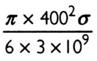
Coul. of electricity.
We can safely make σ = 10 minimum. This would give on the whole structure
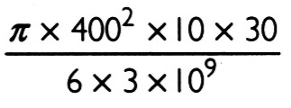
= roughly at least 8/103 Coulombs. Now, if we put capacity as 1000 cm we would have
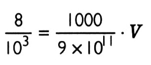
and
This estimate is surely small and we may take safely 10,000,000 volts for 1000 cm capacity.
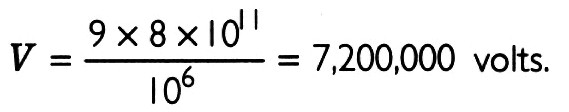
Considering simply earth as ball and leaving out short waves, we have since cP = Cp; V = P = 107 volts; c = 1000 cm. C= capacity of earth = 636 x 9 x 105
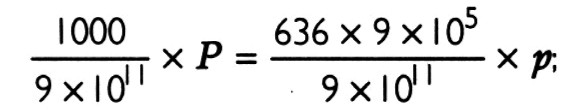
p = simply 16 volts. This means variation of 2p = 32 volts all over globe.

DECIPHERER'S NOTES
Again, the decipherer's proofreader took issue. Using 636 x 106 cm as the value for earth's capacitance, he arrived at the conclusion that p should equal 11 and not 16 volts.
By October, Tesla was quite pleased with his projections for the new tower's output. The decipherer's proofreader had no objections, either.
Oct. 15, 1901
Consideration relative to rate of energy delivery at any point of globe with Long Island apparatus.
Assume that a grounded secondary is employed excited by a primary through which condenser discharges and let both the circuits be in perfect tune so that the secondary system vibrates the same rate whether the primary be closed or open. The form of wave is then as illustrated in diagram. [See Fig. 9.] At a primary begins to excite, at b somewhere in the middle of wave train primary is opened and at c vibrations in secondary cease. In this form of electrical movement the current and emf are in phase, hence the power is always given by the product of these quantities during each half wave, but it must be remembered that the energy is passing from static to kinetic form and consequently the actual power is only that supplied by primary. The secondary circuit increases the amplitude only. But in many cases what is desired is simply a maximum rate. So for instance in telegraphy when a device like a minute spark gap is employed in connection with a tuned circuit. Let us then see what can be expected as reasonable during one swing.
Leicester, North Carolina 28748 USA 9
RARE NOTES FROM TESLA ON WARDENCLYFFE
In previous examples, Emax = 9/8 x 106 volt.
Current = average ; 2000 amp [verify]
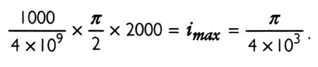
ω = 4π x 105 M = 2 x 10⁵. Hence for largest swing rate of power will be Emax x Jmax = 9/8 x I06 x π/2 x 2000 = 35 x I08 WG. Now on equatorial belt we shall have:
Circumference of belt about 4 x I09 cm. Suppose a strip of ground 1000cm wide λ/2 = 93/200 miles is utilized. The current through the strip will be
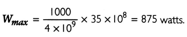
emax = 875 x 4 x 103/π = 11 x 105 volt. Assuming magnifying factor in receiving circuit = 100 we may get with a tuned circuit er = 11 x I07 volt, ir = π/40 amp and Wr= 11π x I07/40 = 86 x 105 watts. Perfectly wonderful!
Note: In addition to these rare notes, there is also an interesting drawing of the underground structure, which circulated on the internet as "Anderson Drawing":

More info on the underground structure here, where a/o the following is said about the underground structure:
"At the base of the edifice, deep below the earth, along the descending spiral staircase, was a network of catacombs that extended out like spokes of a wheel. Sixteen of them contained iron pipes which protruded from the central shaft to a distance of three hundred feet. The expense for these "terrestrial grippers" was notable, as Tesla had to design "special machines to push the pipes, one after the other" [Nikola Tesla On His Work With Alternating Currents, Foreclosure Proceedings] deep into the earth's interior.
"Also in the well were four stone-lined tunnels, each of which gradually rose back to the surface. Large enough for a man to crawl through, they emerged like isolated, igloo-shaped brick ovens three hundred feet from the base of the tower.
"Although the exact reason for the burrows has not been determined, their necessity was probably multifaceted. Tesla had increased the length of the aerial by over a hundred feet by extending the shaft into the earth. Simultaneously, he was able to more easily transmit energy through the ground with this arrangement. It is possible that he also planned to resonate the aquifer which was situated slightly below the bottom of the well. The insulated passageways which climbed back to the surface may have been safety valves, which would have allowed excess pressure to escape. They also provided an alternative way to access the base. Tesla may have planned to fill other shafts with salt water or liquid nitrogen to augment transmission. There may have also been other reasons for their construction." -- Marc Seifer, Wizard : the life and times of Nikola Tesla, p. 291 [After "Dig for Mystery Tunnels Ends With Scientist's Secret Intact," Newsday, Feb. 13, 1979, p. 24, and "Famed inventor, Mystery Tunnels Linked," Newsday, March 10, 1979, p. 19.]

Other links to check:
Write a comment
Beef Shawarma in USA (Sunday, 06 August 2017 17:50)
This blog is so nice to me. I will keep on coming here again and again. Visit my link as well..
President (Tuesday, 03 October 2017 16:17)
Very nice article, I enjoyed reading your post, very nice share, I want to twit this to my followers. Thanks!.
Roofing Replacement | Roof Repair Loganville (Sunday, 05 November 2017 15:55)
It is a great website.. The Design looks very good.. Keep working like that!.
Roofing Replacement | Roof Repair Loganville (Monday, 06 November 2017 12:09)
I appreciated your work very thanks
architects in delhi (Monday, 11 December 2017 14:33)
thanks