 Inventions & Experiments
of Nikola Tesla
Inventions & Experiments
of Nikola Tesla
James Harris Roger - Underground radio
(Static-free Reception & Transmission Underwater & Underground)
http://www.rexresearch.com/rogers/1rogers.htm#ran19
America’s Greatest War Invention
Electrical Experimenter
March 1919
pp.787-789, 834, 835
An invention which has been termed the greatest American war achievement is the Rogers underground and sub-sea radio system. The Rogers system does away entirely with aerial wires, and it is only a mater of months now before all aerial wire systems the world over will be pulled down. Wonderful things have been accomplished by the new system, chief of which is the total elimination of static and the increase of the loudness of received signals, which is often as high as 5000 times the usual strength. Interference, too, is done away with almost entirely now. The Rogers invention is of tremendous importance and revolutionizes our previous ideas on wireless to an extent never dreamt of before. We urge every one interested in radio to read the accompanying authoritative article which discloses the full technical data on the new system for the first time in any periodical.
~~~~~
Top photo [Photos not shown here: poor quality photocopy] shows antenna wires being placed in river by Mr Rogers’ assistants. The inventor has found that his system works just as well under water as through the earth. All of the high power stations in the world, from Nauen and Lyons to Honolulu, are heard in Mr Rogers’ laboratory at Hyattsville, MD, shown in the center and lower views herewith. The author of this article also heard the transatlantic stations coming in loud and clear. Mr Rogers invention is the greatest in the war and is so recognized by the government.
It is revealed now that the Navy Department had been using a powerful undersea wireless during the war. The instruments and system were invented by James H. Rogers, of Hyattsville, MD, and were adopted by the Navy Department as an invaluable addition to the wireless system of the Navy. The two lower photos show the inventor, Mr Rogers, in his laboratory at Hyattsville.
~~~~~~
The greatest invention in the field of wireless telegraphy since Marconi first placed commercial radio-communication on a firm basis by his historic experiments in Italy, and later in England, is without a shade of doubt the latest triumph of radio research --- the "Underground and Sub-Sea Wireless", conceived and developed by an American scientist and inventor, James Harris Rogers. Mr Rogers is known as a second Edison among his towns-people in Hyattsville, Maryland, where he has lived for many years, and now the whole world acclaims him.
Who Is Mr Rogers? ~
James Harris Rogers, practically unknown a few years ago in radio circles, except by a few select radio men who were investigating his invention for the navy Department, has practically become overnight the center of all attractions in the field of science. Mr Rogers is a son of the confederacy and a veteran of the CivilWar. He has followed electrical experimenting ever since and has been a strong devotee of radio telegraphy since Marconi performed his first experiments in this new branch of applied science. He is a refined, cultured southern gentleman who makes you feel at home at once; an invariable attribute of all of the truly great. Mr Rogers was one of the first inventors of the "printing telegraph" and his full-sized working models saw actual commercial service on a circuit between Baltimore and Washington, also in New York, back in 1880. These were seen by the writer and are wonderful pieces of mechanism.
The Rogers laboratory, which comprises several large rooms, is lined on all sides with glass cabinets containing electrical apparatus which he has invented from time to time through his studious career. A novel and original high frequency generator was another of the devices that greatly interested the writer. It employed a jet of water shunted by a large capacity, the stream of water being connected to a high potential source of direct current. High frequency currents of any range up to the limit of audibility, or about 30,000 cycles per second, could be readily obtained with this apparatus. The writer merely cites these facts to substantiate the standing of Mr Rogers in the scientific field. Hundreds of other electrical inventions have been made by this modest genius of the quiet little Maryland town of Hyattsville, and the principal outstanding fact of his work is that he can show you a working model of each of these inventions, unlike many other inventors whose ideas exist only on paper, and which often fall down, miserably, when actually built and tested.
In this connection it is interesting to consider for a moment that not one of the new wireless "static and interference preventers" proposed to the government radio experts during the war, proved practicable in the least.
Official recognition of Mr Rogers as the one and only inventor or "Underground and Undersea Wireless Communication" was soon forthcoming, and here it is in brief. These two official letters of recognition if Mr Rogers’ wonderful and revolutionizing invention represent but a very small fraction of those he has received from radio engineers of high repute in all parts of the world, congratulating him for his masterly work. The Navy Department has just permitted information on the Rogers system to be given out, and how well they kept their secret during the World War during which time this system has been in use by the Navy Department, may be judged by the fact that radio men everywhere are amazed at this feat. The distinguished radio savant Prof. George W. Pierce of Harvard University, congratulated Mr Rogers heartily when he first tested and heard the new system work through salt water, which he at first thought absolutely impossible.
Below we give two letters of official recognition by the Navy Department of Mr Rogers’ accomplishments, which are all that we have space for.
In response to an inquiry from Clarence Owens, director general of the Southern Commercial Congress, Admiral Griffin, USN chief of the Bureau of Steam Engineering wrote under date of December 27, 1918, as follows:
"In reply to your question regarding the originator of the underground radio system, you are advised that Mr. J. H. Rogers of Hyattsville, MD, was the originator of this system. There have been other claimants to methods of underground radio signaling, but none were useful, within the Navy Department’s knowledge to the extent of being a valuable asset to the general scheme of radio communications. The introduction of Mr Rogers’ receiving system marked the beginning of the use of underground aerials for receiving, to great advantage over raised aerials, and has been valuable to the Navy during the war".
Rear Admiral Strother Smith, then Capt. Smith, wrote Mr Rogers on December 7, 1917:
"It is a great pleasure to me to feel that I have been instrumental in bringing the result of your work before the Navy Department and assisting somewhat in putting it into actual practice. Out of the many thousand ideas presented you realize that a very, very small percentage are valuable and it is worth at least a year’s work to get one that I feel will give lasting benefit to the service that I take pleasure in serving".
The Navy Department Interested ~
Through Dr George Lamar and Senator Blair Lee the discovery and the status of the patents were brought to the attention of Secretary Daniels of the Navy, Secretary Daniels ordered inquiry into Mr Rogers’ claims, which showed that his invention worked, and requested Secretary Lane to give special consideration to pending patent applications.
Secretary Daniels then submitted the Rogers system to Rear Admiral (then Captain) Strother Smith, who called into consultation Capt. Hooper. These officers made a thro study of the system and found it practicable. Capt Hooper ordered it installed at New Orleans first and since then it has been employed at Belmar, NJ, and at other stations.
For a decade Mr Rogers has been studying radio subjects, and long before the US entered the war he had experimented with the problem of ridding aerial communication of this static atmospheric activity. He disagreed with all authorities who believed that the air, and not the earth and water, was least suited for wireless communication.
At first Mr Rogers used the earth alone for sending messages to amateurs stationed nearby. Using an audion bulb, he then buried a wire from his laboratory and heard Philadelphia and other stations. Further experiments were conducted at a laboratory near Bladensburg, which he calls "Mount Hooper" in honor of Commander Hooper of the Navy, who rendered excellent service in adapting the invention to the needs of the Navy Department.
When Mr Rogers first stated that messages could be received and sent from submarines when submerged it was unanimously declared to be impossible and the officials of the Bureau of Standards were not alone in this belief, as no less a personage than Marconi declared at a banquet given in his honor in Washington, that when wireless was used on submarines, "it was necessary for the submarine to come to the top in order to catch the ether waves".
To demonstrate more clearly the underground system and to show how it could be used in trench warfare, Mr Rogers constructed an underground station, wholly inclosed beneath the surface of the earth, there being no visual existence outside. This place in Prince Georges country was visited by some very noted men, including Dr Abraham, the head of the French Scientific Commission, who, upon entering the cave at Mt Hooper expressed his amazement and remarked, "The Germans can’t get us here". Lieutenant Paternot, of the French Scientific Commission and the radio representative of France, also heard his native stations talking and expressed equal satisfaction, pleasure, and amazement.
How He Conceived the Underground System ~
The writer asked Mr Rogers just how he came to form the idea of the "Underground and Subsea Radio". He explained that from his very first study of the method of transmitting radio signals by means of an elevated antenna, the question constantly presented itself to his mind --- "If 50 units of power are past into the aerial, then what becomes of the equal amount of energy which passes into the ground". He became so obsessed with his conundrum that he finally asked several prominent radio savants this question. What do you suppose the answer was? --- "It is dissipated in the form of heat in the ground", they answered. But still Mr Rogers thought they were wrong and now he has proved it. Another early idea of his in the theoretical aspect of radio-communication was as follows, and very logical it was, too, as you will agree: He held that if the outer crust of the earth is a conductor, and the surrounding atmospheric envelope is the insulator, then how infinitely better must the former be for the transmission of any form of electric current.
To Mr Rogers’s mind it was more reasonable to suppose that the energy liberated at the base of an aerial was propagated through the earth as well as through the ether above, and that an elevated aerial, at great distance, would be actuated by them as effectually as if the waves reached the same point through the ether above; when the waves through the earth reached the base of the aerial the potential of the plate would be raised and lowered and the aerial would accordingly be energized. Thus was his basic and original idea conceived and settled upon.
Mr Rogers’ first trial with the underground wireless to nearby radio amateurs began about 7 years ago, but his theory of the reason why it must work was formulated over 10 years ago. Further, he conjectured that much less power would be required to propagate a wave or current through the earth’s conducting crust, which for one thing has smaller geometrical dimensions, than to propagate it through the insulating atmospheric envelope alone. See Fig. 1.

The Theory of Operation ~
A number of other radical ideas were entertained for several years by Mr Rogers, and in the course of time he has found that his ideas were correct --- it worked! It worked! And now the radio experts far and wide are holding a post mortem inquest on their theories and how it all happened. To start with, Mr Rogers stated, "special credit is die the following gentlemen, who have remained enthusiastic and sincere in all the tests and installations made of my underground radio system through all the trials and disappointments of its development, even when the system seemed to be unworkable. Their perseverance and high skill in the radio art has hastened the official endorsement and the installation of the buried and submerged antenna":
Commander A. Hoyt, D Sc., USN; Dr L. W. Watson, Bureau of Standards; Admiral Strother Smith, USN; Commander Hooper, USN; G.H. Clark, Expert Radio Aid, USN; Dr George W Pierce, of Harvard University; and Ensign A. Crossley, USN, who ahs actively engaged on the installation of the Rogers system at the Great Lakes Radio Station, New Orleans, New London, CT, and Norfolk, VA.
Like many other great inventions the exact mode operation is hard to ascertain and define. The views of Mr Rogers on the operation of this wireless system are briefly defined as follows: ---
First, that the electrical energy liberated at the base of an antenna will be propagated through the earth even in the absence of etheric space waves above, if such a condition were possible, and which in reality does occur when great distances are signaled over, so he believes. Second, that the propagation of earth waves no more depend upon the ether waves above the surface than these etheric waves depend upon the earth waves. Further, that both waves are propagated simultaneously, one above and another below the surface of the earth, and that at the initial start each is dependent upon the other, although thereafter neither is dependent upon the other. Furthermore, Mr Rogers believes that the ether waves gradually die out in intensity in proportion to the earth’s curvature, and the distance over which they are propagated, and that at great distances the ether space waves do not have any appreciable effect upon receiving appliances, and that these are energized solely by the energy transmitted through the earth.
These ground currents travel with the speed of light and are picked up at the receiving station. The space waves persist for an appreciable distance, which accounts for airplane-to-airplane and airplane-to-earth communication, but it is the belief of Mr Rogers that in such long-distance radio transmission as half-way around the globe (12,000 miles) that it is the ground wave current that does the work, and that the free space wave above the surface of the earth never reaches the station, due to the high resistance of the atmospheric envelope.
One of the Naval experts present mentioned that it had been found that the penetration of the ground wave component increases with an increase in wavelength. This is an important fact and helps to explain the operation of this new radio system, with its aerials buried in the ground. He also mentioned that "Radio to Mars" or other planets would be impossible, if we are to believe in the well-known "Heaviside" ionization layer, surrounding the earth at a height computed at from 30 to 50 miles, for no etheric wave can pass this layer without being reflected back to the earth, or at least restrained within this passageway.
Rogers System Eliminates "Static" & "Interference" ~
Mr Rogers stated that his underground antenna, in itself, did not solve entirely the static or interference problem, but made it the nearest approach to this ideal condition -- the goal of all radio engineers -- than had ever been accomplished before. This problem has, thanks to a new arrangement perfected by Comm. A. Hoyt Taylor, D. Sc., been solved and static and interference have been practically eliminated, for all-year-round radio service. Think what an advance this means! Further, there is no rise and fall in the signal strength during the night or day, at any time of the year, due to the sun’s ionization effect, as is the case where elevated antennae are employed. The US Naval reports and tests made with the Rogers ground aerial in comparison with the usual form of elevated aerial, several of which are appended herewith, show the incomparable efficiency of this new radio system.
What The Facts Show ~
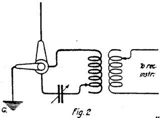
First we will mention the test which Mr Rogers and a naval officer conducted for the writer. The apparatus used in these tests are shown in the accompanying photographs. They included several tuning inductances, variable condensers, a one-step audion amplifier (single Audiotron bulb only!) and two pairs of Baldwin phones (telephone receivers). This apparatus was connected up to one of Mr Rogers’ latest buried antennas --- a single rubber-covered, stranded copper cable, extending westward for a distance of 4,000 feet, so as to be in a plane with the high-power European radio stations. This cable is encased in iron pipe (gas pipe), each 20-foot section of which is insulated from the abutting sections by means of a rubber hose (garden hose) slipped over the pipe ends for a few inches. This is buried in a dirt trench about 3 feet deep, filled in with soil. The cable is insulated at the free end and is connected up as in Fig. 2. The rubber covered wire alone has been used in all sub-aqueous tests, and gives fine results when simply buried in the ground, the decay not being so rapid as probably would be imagined. This latest aerial in the iron pipes is a new development and experiments are still going on with it. It works wonderfully well. The 4,000 foot aerial here described is best suited to receiving radio lengths of 6,000 to 16,000 meters. For shorter wavelengths aerials of smaller dimensions are employed.
"Here’s the Lyons station in France", said Mr Rogers. A turn of the knob on the specially calibrated condenser, and there was Lyons (France), sure enough. Static and interference were unheard. Next the great stations across the broad Atlantic, at Nauen, Germany; Carnarvon, Wales, (England; and Rome, Italy, were heard with equal loudness and clarity. This laboratory station, which has picked up practically all the high power stations on the globe. American stations are then picked up by changing the wavelength, and finally a test was made on a short (250 feet in length) buried ground antenna, adapted to receiving wavelengths of 200 to 800 meters. Wireless telephone messages were picked up from Washington, a distance of about 7 miles. It is most interesting to note at this juncture, as other tests have shown, that a radio message from an airplane cannot be picked up on the underground aerial, until the plane is directly over the station. This would seem to prove two things: first, that the short waves sent out by the airplane radio set do not penetrate into the ground very far, if at all, --- and second, that airplane radio transmission and reception are effected solely by etheric waves.

Referring to Figures 3 and 4, we find several interesting points. Figure 3-A shows how a double ground aerial is sometimes connected. Also, as in the case of Mr Rogers’ test station, several sets of these buried antennae are best employed, distributed about the station as shown in Fig. 3-B.
The Rogers underground antenna system has been used at the Belmar, NJ, station during the war with most gratifying results, as reported by the Navy Department, and its successful and unfailing operation during the 24 hours of the day, resulted in trebling and quadrupling the capacity of this great trans-Atlantic highway of intelligence communication. The official reports in connection with the work accomplished with the underground Rogers system at Belmar state that not a single word of communication was lost during the reception of thousands of important messages from Europe. The station at Tuckerton, NJ has also been equipped with the Rogers underground aerial system and all of the larger stations of the Allied powers in Europe have been copied successfully through the 24 hours, at this point also.
Submarine Wireless ~
Perhaps the most interesting tests of all are those which were made on submerged submarines in salt water! The aerial in this case was of heavily insulated stranded cable, stretched from stem to stern as Fig. 4-A illustrates. The two aerials were brought down through the conning tower and joined to the receiving apparatus. A second form of aerial is illustrated in Fig. 4-B, where the insulated aerial wires are placed in iron pipes within the submarine. Here are the results of some of these tests, which do not include the transmitting tests to the submarine from a ground antenna on shore. When submerged 8 feet, the German station at Nauen was picked up by the submarine while lying off the American coast! Submarines have, in other official tests, picked up distant stations when submerged 21 feet, on a wavelength of 12,600 meters or greater wavelengths.
One of the naval officers, who has had much to do with the testing of the Rogers system, stated that experience had demonstrated that in fresh water the submerged antenna may be placed at any depth. Salt water acts differently, but the aerial may be submerged at any desired depth for wavelengths above 10,000 meters.
The same officer, who has made a close study of all American and European work in radio, explained how the best work ever done in radio was accomplished at the Great Lakes Naval Station, on the shores of Lake Michigan. Figure 5 gives the general arrangement of the station. The test station was on the beach and acted as a "remote control" station for standard station at A. The shortest distance between a "receiving and control station" in the naval radio service heretofore has been 36 miles. Here a distance of 600 feet only separates the elevated aerial of the main station from the submerged Rogers antenna terminating at the test station. Said he, "Now let the inventors of ‘static and interference’ preventers trot out their little pets, and show what they can do! Here’s what this station actually did on schedule service: with 48 amperes, at 4,000 meters wavelength, being radiated in the elevated main antenna --- the beach station, only 600 feet away, was picking up Nauen on 12,000 meters, and New Orleans on 5,000 meters, without any interference or static --- all on the Rogers sub-aqueous aerials. These were rubber-covered cables spreading in different directions, any one of which could be used, and laying 50 feet deep in the water at their outer extremities.
Imagine such a wonderful performance! But this is not all. The official tests show that the station at Cavite, PI, 8,100 miles away, was received regularly on the Rogers aerials at the Lake Michigan Station, on schedule service.
Transmitting On Underground Aerials ~
Tests were made by the naval experts, as well as by Mr Rogers in his very first experiments in transmission from a ground or underwater antenna. These were all successful. It is only a matter of properly insulating the antenna so that it will not break down under the high potential applied to it by the transmitter. The early tests by the inventor were made with a one inch spark coil to the Bureau of Standards Radio Laboratory, a distance of 7 miles, the received signals having an audibility of 2,000, i.e., 2,000 times the strength of a clear, readable signal. The audibility of the signals at the Washington Navy Yard was 1,000. The transmitting tests at the Great Lakes Naval Station were made at first with a low power Oscillion bulb transmitter and later with a Clapp-Eastham hytone set. An elevated amateur style antenna of two wires was strung up between two houses 38 miles away. Clear signals were received with an audibility strength of 2,000. The ignition cable used for the aerial finally punctured, but even then the signals received were four times louder than the best amateur transmitter could send on a regular aerial, as tests proved.
Official US Naval Tests of Underground Reception ~
In general (relating to the Rogers system), the point of interest lies in the use of wires buried in the ground, for both the transmitting and the receiving antenna. For instance, in receiving, a wire buried one foot below the surface of the earth extends for several hundred feet south of the receiving station, and a similar wire north, the receiver being located between the pairs of wires. The ordinary receiver was used. With this arrangement, signals from Darien, Nauen, and all Atlantic stations were received.
Tests at New Orleans Station ~
Federal receiver used on main antenna, Western Electric receiver used on underground antenna, 1,400 feet buried wire. The "Aud" refer to audibility.
Station Antenna:
Main
Underground
Wavelength ~ Signal Aud ~ Static Aud. ~ Sig. Aud. ~ Stat. Aud.
San Diego 9800
1200 1000
750 15
Arlington
7500 2000
3000 1500 50
Impossible to read Arlington on the elevated antenna on account of static interference. United Fruit Co station of New Orleans interfered with signals from Arlington on main antenna, but offered no interference on underground antenna... [Missing Text ]
Of particular interest is the fact that when static prevents reception on the main antenna, reception can be continued on the underground antenna. This has even been done during a severe lightning storm, when the main antenna would have been dangerous without grounding. Reception is also directional and permits of avoiding interference to some extent by using wire "off direction" of an interfering station.
Strays are as a rule practically absent. On a few occasions, strays have risen to an audibility in excess of 5,000 on separate cracks, but even in this case, reception of signals, although a little difficult, was not interrupted. On these occasions it was necessary to ground both of the elevated aerials at the main station.
Considering the matter of strays, it can be said that on four or five occasions marked by tremendous storms, that strays rose to an audibility in excess of 10,000 at the beach station. Even in this case, however, signals from boats within 100 miles and from shore stations such as Milwaukee, were usually readable, because the strays while very loud, were nowhere near as numerous as on the elevated aerial..
There seems to be no appreciable advantage in using more than one wire --- No. 12 weather proof insulated.
The experiments at Great Lakes confirm the work of the Bureau of Standards on the importance of adequate insulation of the wire. If the wires are grounded a the ends, it does not necessarily make much difference unless they are adjusted to the optimum wire length; but if properly adjusted to this length, grounding of the wires produces a diminuation of the signals, which, however, even with the intentional grounding of the two ends, still leaves them 50% of their maximum value. Therefore, while the question of insulation is important, it does not mean that the system will fail entirely if the insulation becomes faulty.
The Rogers Underground Aerial For Amateurs
Electrical Experimenter
June 1919
Since the publication of the original article on the Rogers Underground Wireless System, published in March, 1919, the Editors have been besieged by hundreds and thousands of letters from radio experimenters in all parts of the world, asking for data on the construction of the Rogers Underground Aerial suited for the requirements of the Wireless Amateur. The original article contained a great deal of valuable data, which should be carefully read and digested by every radio man, whether he be a student or a professional. In the present article an effort has been made to answer some of the questions which have seemed to annoy the average radio "bug" considerably, --- especially those residing in cities where it is difficult and frequently impossible to bury an aerial longer than a few feet. We may say right here, that for those experimenters so situated, there is a solution, or in fact, two solutions, namely --- to use a spiral antenna, such as has been tried out successfully in US Navy tests on the Rogers system, and which spirals may be buried in the ground a few feet, or placed in a well or a body of water; and secondly, for the experimenter who is not allowed to disfigure an apartment house or other dwelling with a ugly-looking aerial, there is a newly developed loop antenna, which can be used right in the radio room. Indoor aerials have been greatly perfected during the war, and now by means of greatly improved and highly sensitive wireless receiving instruments and amplifiers available, particularly those using audions as detectors and amplifiers, they are excellent, and satisfactory results are obtainable by means of a concentrated loop or spiral antenna, small enough to be placed in the radio laboratory.
For the present, we will listen to the sound advice given by our mutual friend, Mr James Harris Rogers, on some of the practical outstanding features of his underground system, used in conjunction with straight-away single wire underground aerials, as well as loop aerials. Among other things, Mr Rogers has the following to say regarding the installation of simple underground aerials:
Mr Rogers Talks to the Amateurs ~
"The first installation of my underground antenna was made in the woods about a mile from my laboratory and consisted in burying wires in the earth; the wires radiated from the station as the spokes of a wheel, --- some wire bare and some insulated; their lengths varied from 200 to 1,000 feet. ( Figure 1)

"It is obvious that a number of persons can receive at the same time, one operator to each wire. There is no interference. Figure 1 shows 8 wires and a bipolar selector swirch connected to the primary receiving circuit. With this switch any individual wire may be grounded, or any two wires may be used. Bare wires give the loudest signals but static is more pronounced. The deeper the wires are buried, the better the signals, with a corresponding reduction of static. Short wires show a remarkable degree of directivity; long ones to a lesser degree and in proportion to their length. (See Figs. 2 & 3)
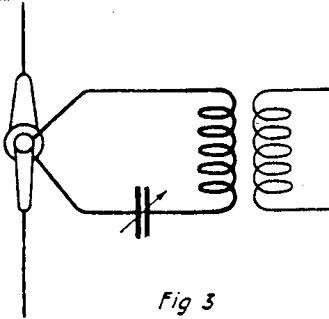
"When using two wires at right angles to each other, signals are heard from any direction. (Fig. 4)

"The system works best in fresh water or very wet earth. The primary circuit should have a variable condenser ) 0.001 mfd or higher capacity) in series. When insulated wires are covered with metal, lead, iron, etc., some remarkable results are obtained. These wires may be entirely enclosed in an iron pipe, for instance (Fig. 5), or the joints may be connected by rubber hose". (Fig. 6)


"Regarding the tests with loops I will state briefly that I have successfully tried different forms and sizes.
"I first had a well bailed out and lowered a loop antenna into it; the well was 50 feet deep (See Fig. 7). The signals were as loud at the bottom as when above the earth. I next had the well filled with water and the results were the same, excepting that the note of the sending station became higher and higher as it was lowered. Upon revolving it around, I found the directional characteristics were the same in the water as when out. These tests were made about 2 years ago, and I at once realized that the loops or cages could be used in the dugouts of France, or on submarines when submerged.

"Regarding the dimensions of loop antennae used on submarines, these coils measure about 3 feet square in some instances. The wires are very heavily insulated and placed in a box filled with pitch, the connection are led below and the coil can be revolved for directional observations."
Kind of Wire Used for Underground Aerials ~
Most of the inquiries from Radio Experimenters and those intending to install experimental stations, and wishing to make use of the "static-proof" Rogers underground antenna, on which signals may be received even through a thunderstorm, indicate that the greatest problem to solve seems to be the size and the kind of wire to be used, and how it shall be buried. Some very excellent results have been obtained in experimental work carried out at one of the leading American universities with aerial conductors laid on the ground, and where the experimenter has the time and space to try this out, he may gain some useful and valuable knowledge by experimenting in this direction. Ordinarily the wire, of whatever kind it may be, as used when installing the Rogers underground aerial, is buried about 3 feet deep in the earth. For most amateur requirements, the wire need only be about 100 to 200 feet long, and so the digging of the trench is not such a great problem; in fact, it can be plowed open, at least part of the depth, and where rivers, brooks or ponds are available the insulated wire can be placed in them directly and allowed to rest on the bed.
Regarding the choice of wire to be used, it becomes evident that even bare copper or other wire may be utilized when desired, as Mr Rogers has pointed out in the above contribution. The size of this wire should be about #12 or 14 B&S gage, the heavier the better.
The official US Navy report of tests on the Rogers Underground System mention that no increased efficiency is obtained by using more than one wire, and that this may be a # 12 or 14 B&S gage, weather-proof or rubber-covered copper conductor. In any case, the free end of the wire should well taped, and preferably covered with some rubber cement, so as to keep it insulated. Experiments have been tried both by Mr Rogers at his Hyattsville MD laboratory, and also by the Navy Department, with underground aerials in terra cotta pipes, but this construction is rather expensive, and the results obtained do not justify its use.
Other forms of wire used both by Mr Rogers and the Navy Department experts include lead-covered telephone cable, which is, of course, thoroughly damp-proof, while a conductor holding considerable favor with the inventor is the heavy rubber-covered, high-tension, auto-ignition cable. This is highly efficient for aerial requirements, as it is stranded and therefore of low high frequency resistance.
In any case, a little common sense and logic will give the answer to many of the simple problems arising in connection with the installation of these aerials, such as, for instance, the length of aerial to be used for a certain range of wavelengths. It is manifest that the longer the wavelength to which it will properly respond. Considering that an antenna is used having a length of, say, 150 to 200 feet, then practically all the shorter wavelengths up to 600 meters and more should be readily picked up on this antenna, especially with the variable condenser hooked up in series with the primary of the loose coupler, as shown in the accompanying diagrams. Naturally the wire buried in the ground has a higher electrostatic capacity than the old style antenna wires, elevated 40 to 50 feet above the ground, and we can reduce this capacity as desired, so as to tune any certain wavelengths, by connecting another capacity in series with it: in exactly the same manner as short wave lengths are tuned in on the regular elevated aerials, by connecting a variable capacity in series with the antenna circuit, and the primary of the loose coupler. Long wavelengths are tunable by using large condensers and loose couplers preferably.
Spiral or Loop Aerials ~
As shown in the diagram, Fig. 7, interesting results were obtained with a spiral antenna, composed of a dozen or so turns of insulated wire, such as a high tension cable or # 14 RC solid conductor lowered into a well. Both with and without water in it.
As pointed out in the original article on the Rogers underground system in the March issue, very promising results have been obtained in transmitting with the underground antenna, and Fig. 8 shows how a small transmitting set was operated with such an aerial, coupling the exciting or spark gap circuit with the antenna oscillatory circuit by means of a two-coil oscillatory transformer, L, C. In this case two metal plates, about one yard square, are placed in the earth adjacent to the well, one of which connects with the secondary, S, of the oscillation transformer, while the other plate connects with the free end of the spiral antenna.
If the spiral antenna is used, it should be placed on its vertical axis, and it should be placed in the vertical placed in the vertical plane as shown as shown in Figs. 7 and 8. Excellent results have been had should be obtained in transmitting with the underground antenna, with the usual insulation incident to the form of conductors above specified, where the transmitting set is one employing an audion oscillation generator. The voltage in this case will not be extremely high and special precautions need not be taken to provide extra heavy insulation on the buried antenna. The wire in such a case, however, should be especially. Official tests by the US Navy have shown transmission by radio over 50 miles with the Rogers underground antenna. The wire in such a case, however, should be especially well insulated to stand the higher voltage.

Regarding loop aerials in general, it would appear that we can expect a great deal from them, as some of the really remarkable results achieved during the war would seem to point out. The number of turns and the amount of wire to be used in a spiral wire to be used in a spiral antenna, such as shown at Figs. 7 and 8, will vary of course for different wavelengths, etc., and here is where the radio Amateur will have a chance to carry out some original experiments, which may net him some real knowledge, fame and money. Another form of loop antenna, so-called, and which has been tried out several years ago with such success that European stations could be copied in a laboratory located in Florida, is one composing a square form, several feet in height. This was used, as just mentioned, to receive stations using fairly long wavelengths, say from 8,000 to12,000 meters. Here the insulating form was wound with a layer comprising several hundred turns of insulated wire. This antenna was successfully used in some tests made by Marconi radio engineers at a laboratory in Florida several years ago. Trans-Atlantic radio reception was effected at the radio laboratory of Union College, Schenectady NY, just prior to America’s entrance into the world war. This aerial comprised about two dozen turns of # 14 or 12 bare or RC wire, mounted on porcelain know insulators screwed on the inside wall of the laboratory. The turns were spaced about 3 inches apart. The inside turn was 3 feet square. Flexible leads, fitted with clips, serve to connect as many turns as desired.
Unfinished - Pending article
Other links to check:
Write a comment